15.02.04.
PROCEDURE ANALYSIS OF
MEASUREMENT OF ELECTRIC POWER CONSUMED BY THE WATER ELECTRIC GENERATOR OF HEAT
Ph.M. Kanarev
E-mail: kanphil@mail.kuban.ru
We have received positive decisions concerning
the first applications for issuance of the patents for high efficiency devices
generating additional heat energy. Time comes when other investigators join our
search. Innovative technology mastering process will move faster if the
beginning investigators know the most complicated matters that block
commercialization of these devices. That's why we have decided to begin
publication of the patented diagrams of the cells of the water electric
generator of heat with the description of the most complicated matters that
will restrain its commercialization. The measurement procedure of electric
power consumed by the water electric generator of heat in household and
industry is one of such matters. That's why we analyse this procedure in detail
using concrete experimental data.
The measurements have been carried out
using a laboratory model of the most effective cell of the water electric
generator of heat (Fig. 1). A diagram of this cell will be published when a
positive decision or a patent is obtained.
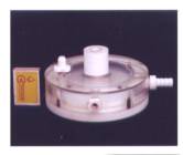
Fig. 1. Cell of the water electric generator of
heat
A diagram of the experimental assembly is shown
in Fig. 2.
Fig. 2. Diagram of the experimental assembly: 1
– a tank for the solution; 2 – thermometer; 3 – electronic scales; 4 – solution
feed duct; 5 – rotameter; 6 – solution feed regulator; 7 – cell of the water
electric generator of heat; 8 – thermometer; 9 – heated solution drain; 10 –
intake tank
Voltage and current at the input of the cell of the water electric
generator of heat were measured with the help of two sets of the devices: a
voltmeter of 0.2 accuracy class (GOST 8711-78), an ammeter of 0.2 accuracy
class (GOST 8711-60) and ACK-20222 electronic oscillograph.
In order to reduce heat losses that were not taken into consideration in
the experiment, a solution temperature difference before its heating in the
cell and after heating was maintained as not very high: Dt=21°C.
The results of the experiment are given in Table 1.
Table 1
|
Indices |
1 |
2 |
3 |
Average |
|
1 - mass
of the solution, which has passed through the generator |
0.600 |
0.624 |
0.600 |
0.608 |
|
2 -
temperature of solution at the input of the generator |
21.0 |
21.0 |
21.0 |
21.0 |
|
3 -
temperature of the solution at the output of the generator |
41.0 |
41.0 |
41.0 |
41.0 |
|
4 -
temperature difference of the solution |
20.0 |
20.0 |
20.0 |
20.0 |
|
5 -
durability of the experiment |
300.0 |
300.0 |
300.0 |
300.0 |
|
6 -
reading of voltmeter |
5.0 |
5.0 |
5.0 |
5.0 |
|
6’ -
readings of oscillograph |
4.8 |
4.8 |
4.8 |
4.8 |
|
7 -
reading of ammeter |
0.60 |
0.60 |
0.60 |
0.60 |
|
7’ - readings
of oscillograph |
0.60 |
0.60 |
0.60 |
0.60 |
|
8 -
electric power consumption according to the readings of voltmeter and
ammeter, |
0.90 |
0.90 |
0.90 |
0.90 |
|
9 –
heated solution energy |
36.48 |
37.94 |
36.48 |
36.97 |
|
10 - COP of the generator |
40.53 |
42.15 |
40.53 |
41.07 |
As energy efficiency of the cell proved to be significant, we decided to
duplicate the readings of the voltmeter and the ammeter using the oscillograph
readings. When we obtained the oscillograms, we applied to a specialist in
measuring systems and devices. He was so kind to agree to help us. He processed
the oscillograms and sent a method of processing and its results. He advised in
his letter that we determined electric power at the cell input correctly. In
token of respect we included him as a co-author in the first article where we
published the method suggested by him and the results of its application.
As a speciality of measuring systems and devices is rarely met, and its
master is a person with a long length of service (he is a pensioner), we have
treated him with great respect. All our further activities were based on his
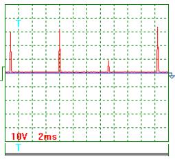
authority. The oscillograms of voltage (Fig. 3) and current (Fig. 4) as well as
the method of their processing are given below.
Pulse scale is 10. Average voltage amplitude
(Fig. 3): Uаср = (29+31+8+33)x10/4 = 252.5 V.
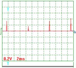
Current magnitude was determined as voltage
drop on the resistor with resistance of 0.1 Ohm. Taking this into account,
average current amplitude is (Fig. 4):
Iаср
= (1.7+0.8+1.7+2.1) x 0.2x10/(4x0.1) = 31.5 А.
Pulse repetition period Т = 7.4 ms.
Pulse duration tp = 0.28 ms.
Pulse frequency f = 1000/7,4 = 135.14 Hz.
Relative pulse duration S = 7.4/0.28 = 26.43.
Pulse ratio Z = 0.5/26.43 = 0.019.
Average value of pulse voltage Ucр
= 0.019 x 252.5 = 4.80 V.
Average value of current in pulses Iср
= 0.019 x 31.5 = 0,60 A.
|
Fig. 3. Tension |
Fig. 4. Current |
It is clear from these data that the difference between the readings of the
voltmeter, the ammeter (Table 1) and the oscillograph do not exceed 5%. It is a
reason why we consider the results being obtained as the correct ones.
But later on the author the technique being suggested to us advised that
he has doubts concerning correctness of the determination method of energy
consumed by the cell of the water electric generator of heat.
As I am a supervisor of studies, I myself have had to carry out a
detailed analysis of the measurement procedure of power consumed by the cell of
the water electric generator of heat. The results of this analysis are given
below.
Fig. 5. Structural diagram of measurement of electric values of the water
electric generator of heat: 1 –cell of the water electric generator of heat; 2
– electric oscillograph; 3 – pulse generator; 4 – voltage pulse; 5 – current
pulse; the rest units of the diagram correspond to conventional designations.
In order to facilitate the process of analysis, we had to elaborate a
diagram that we called a structural one conventionally (Fig. 5). During the
experiment in addition to the data given in Table 1, voltage and current were
registered before the pulse generator (Fig. 5, pos. 3). Voltage before the
pulse generator was equal to supply-line voltage, i.e. 220 V. Current magnitude
remained the same and was equal to 0.60 A.
Average value of voltage of 5.0 V and average value of current of 0.60 A
(Fig. 5) at the input of the cell (1) of the water electric generator of heat
are written in the diagrammatic presentation of the voltmeter and the ammeter.
As shown in Fig. 5, average amplitude of voltage pulses was 252.5 V with
average value of voltage of 5.0 V; average amplitude of current pulses was 31.5
A with average value of current of 0.60 A. Pulse duration was 0.00028 s with
relative pulse duration of 26.43 and
pulse ratio of 0.019.
In accordance with the readings of the voltmeter, the ammeter and the
oscillograph, power at the input of the cell of the water electric generator of
heat is P0 = 5 x 0.6 = 3.0 W on the average. Taking this into
account, energy efficiency is 41.07 x
100 = 4107% (Table 1). The same result is obtained while processing of the
oscillograms.
It is known that a determination of the values of voltage and current in
electric circuits with complicated electric pulses (Figs 3 and 4) with the help
of the oscillograms is considered to be the most reliable though not the most
accurate one. That’s why the oscillograph readings, which differ from the
readings of the voltmeter and the ammeter duplicating it by 5%, are considered
to be unquestionable. On this basis, a conclusion is drawn that an index of
power efficiency of the processes, which take place in the cell of the water
electric generator of heat, is nearly 4000%.
In order to be sure that the result being obtained are reliable, it is
desirable to duplicate the reading of the voltmeter, the ammeter and the
oscillograph with the help of one more, nicer device. An electronic energy
meter is the device, but we have no such meter. But we know a principle of its
operation, and we can calculate a theoretical result that it is sure to
display.
First of all, the electronic meter will register energy of each pulse.
As energy is proportional of pulse
area, the electron energy meter will determine area of each pulse of voltage
and each pulse of current separately (Figs 3 and 4). Let us assume that it will
multiply the obtained areas of pulses of voltage and current by quantity of
pulses during one experiment (300/0.0074) = 40540.54. Later on, multiplication
of total area of voltage pulses by total area of current pulses should give a
value of energy consumed by the cell (1). Taking into consideration a
triangular form of the pulses, we’ll have:
voltage pulse area
252.5x0.5x0.00028x40540.54=1418.92;
current pulse area
31.5x0.5x0.00028x40540.54=178.38.
If energy consumed by the generator of heat is registered in such a way,
its value will be E = 1418.92 x 178.38 = 253.1 kJ. It is clear that it is an
erroneous result, because it is greater than the readings of the devices
installed before the pulse generator 220 x 0.6 x 300 = 39.6 kJ. What is the
core of the introduced error? In order to find it, let us determine this energy
using the pulses of voltage and current for the determination of power being
implemented by the cell. For this purpose, it is necessary to find the total
area of the pulses of voltage and current per second and to multiply it. Quantity of pulses per second is equal to
pulse frequency of 135.14 Hz. The total area of voltage pulses per second will
be 252.5x0.5x0.00028x135.14=4.78 V. The total area of current pulses will be
31.5x0.5x0.00028x135.14= 0.60 A. It is clear that these values coincide with those
that have been obtained when processing the oscillograms. Power implemented by
the cell will be equal to 4.78x0.60=2.87 W; energy consumed by it from the
supply line will be 2.87x300=0.86 kJ. Energy efficiency of the process will be
36.97/0.86=42.50. The voltmeter and the ammeter, which are placed before the
cell, confirm this result. In Table 1, this value is equal to 41.07.
Now it is easier for us to find an answer to the question: why do the
instruments arranged before the pulse generator (3) indicate that the pulse
generator and the cell consume 39.6 kJ in total during the experiment, and the
consideration of all pulses of voltage and current gives the value of 253.1 kJ?
In order to give a reply to this question, let us pay attention to the
fact that (Fig. 5) current value is the same for the whole circuit, and voltage
values are different. Before the pulse generator (3), voltage value is 220 V;
after it, before the cell, it is 5.0 V. It appear from this that while
calculating energy consumed by the cell by means of area count of pulses of
voltage and current we should take overall area of voltage pulses only and
multiply this are by current value being the same for the whole circuit, i.e.
by 0.6 A. We’ll have 252.5 x 0.5 x 0.00028 x 0.6 x41095.98 = 0.87 kJ. Energy
efficiency of the process will be 36.97/0.87=42.50.
Thus, if we record the energy consumed by the cell with the help the
electronic energy meter arranged before the cell, we’ll get the same result as
the one being obtained due to the readings of the voltmeter, the ammeter and
the oscillograph.
Other confirmations that the energy efficiency index of the cell of the
water electric generator of heat exceeds 4000% are unnecessary. Under
laboratory conditions, this index registration is stable and safe.
A question emerges: can the existing electrical-type instruments
arranged before the pulse generator prove this efficiency (Fig. 5, pos. 3)?
It can be early seen (Fig. 5) that with coefficient of performance of
the pulse generator being equal or near a unit the ammeter arranged before the
pulse generator (3) will indicate 0.60 A and the voltmeter will indicate 220 V.
As a result, power implemented by the pulse generator (3) and the cell (1) will
be P1 = 220 x 0.60 = 132 W. In this case, energy efficiency of the
cell of the water electric generator of heat will be less than a unit
(36970/300=123.23)/132=0.93 taking into consideration energy of the heated
solution (Table 1).
Thus, even with coefficient of performance of the pulse generator (3)
being equal to a unit the readings of the instruments arranged before the pulse
generator and after it demonstrate approximately 40fold difference. A question
emerges: what instruments give a result corresponding to actual consumption of
energy consumed by the cell of the water electric generator of heat? The
instruments arranged before the pulse generator (3) or the instruments arranged
after it? What is the essence of physics in a difference of these readings?
In order to give an answer to this question, let us consider physical
processes that take place while measurement of voltage and current before the
pulse generator (3).
The readings of the voltmeter arranged before the pulse generator (3)
are greater than the readings of the oscillograph and the voltmeter arranged
before the cell (1). It takes place due to the fact that voltage before the
pulse generator is always equal to supply line voltage of 220 V.
Let us pay attention to the fact that one pulse (6) of rectified current
with duration of 0.01 s is shown in Fig. 5. In the same Fig., a voltage pulse
(4) with duration of 0.0003 s is shown. The pulse generator separates it from
the whole pulse with duration of 0.01 s and sends it to the cell. Strictly
speaking, the remaining area under the curve of a rectified pulse with voltage
of 220 V should be reduced by a value corresponding to the area of the pulse
that has gone to the cell (1), and it should correspond to voltage 220-5=215 V.
But this difference is compensated at once by supply line potential, and this
area of pulse with duration of 0.01 s remains corresponding to voltage of 220
V.
Thus, any measuring instruments
arranged before the pulse generator (3) will register 40fold greater power than
the instruments arranged before the cell (1). Now we know why. Because the
instruments arranged before the pulse generator (3) refer current of 0.60 A not
to the value of voltage pulse (duration of 0.0003 s), which has gone to the
cell of the water electric generator of heat, but to the whole voltage (6)
pulse (220 V) with duration of 0.01 s.
Now we can start finding the reply to another question: can the obtained
efficiency be implemented under the industrial and household conditions in
order to save energy?
As the electric network is a closed loop system, current of 0.6 A will
run in this system (with voltage of 220 V) via all electric power meters to a
turbine of the power station generator. As a result, all meters will register
power implemented by the pulse generator (3) and the cell (1) together, i.e.
132 W. These are the features of electric circuits. We'll get no energy saving.
There are two contradictory results: incontestable energy efficiency of
the cell of the water electric generator of heat that is equal to almost 4000%
and incapability of the electrical network to accept this efficiency in order to
save energy. The main reason of this contradiction is in the fact that the cell
consumes energy in the form of short-duration pulses of voltage and current,
and there are no such pulses in the electrical network.
What if we forego from the pulse generator and work out an electric
power generator that will produce energy in the form of such pulses (Figs 3 and
4), which are consumed by the cell? Such generator should have no electric
coupling with the whole electrical network. In this case, power of 3.0 W
implemented by the cell will be on the shaft of such generator. If we make this
shaft as a common one with the shaft of the electric motor energizing the
generator, the common shaft of the electric motor and the generator will give
3.0W to the cell. Power taken by the electric motor from the network will be
approximately the same (taking into account the losses).
Conclusion
The voltmeter, the ammeter and the oscillograph arranged before the cell
of the water electric generator of heat determine energy, which is consumed by
them, in a correct way.
Energy efficiency of the cell of the water electric generator of heat
amounting to 4000% is registered persistently and safely under the laboratory
conditions.
High energy efficiency of the water electric generator of heat can be
implemented in modern electrical networks via an individual generator producing
electric energy in the form of pulses of voltage and current consumed by the
water electric generator of heat.
References
1. Kanarev Ph.M. The Foundations of
Physchemistry of Micro World. The Third Edition. 2003. (In Russian). http://Kanarev.innoplaza.net
2. Kanarev Ph.M. The Foundations of
Physchemistry of Micro World. The Fourth
Edition. 2004 (in English). http://Kanarev.innoplaza.net
3. Ph.M. Kanarev. Prediction
of Evolution of Fundamental Physical Investigation. 2004. 160 pages. (In
Russian). http://Kanarev.innoplaza.net Book 2.
Webmaster: j_hartikka@hotmail.com
Suggested reading for experimenters wanting to repeat the ‘Kanarev Effect’: Part 4 (2.3
Mb) of "The Foundation of Physchemistry of Micro World", the
Fourth edition.
Procedure Analysis of Measurement of Electric Power
Consumed by the Water Electric Generator of Heat
by Prof. Kanarev: http://Kanarev.analysis.innoplaza.net
<< Kanarev´s Page